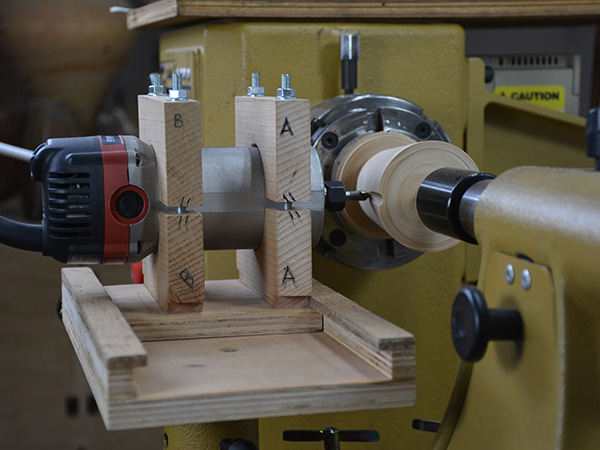
Several years ago, my teacher, Eric Tan, designed a jig to hold a router on the lathe, and I have been intrigued ever since I made my first groove on a turned box. Since then, I have been trying to find new ways to incorporate the router with the lathe as part of the turning process and as a way to have more design possibilities.
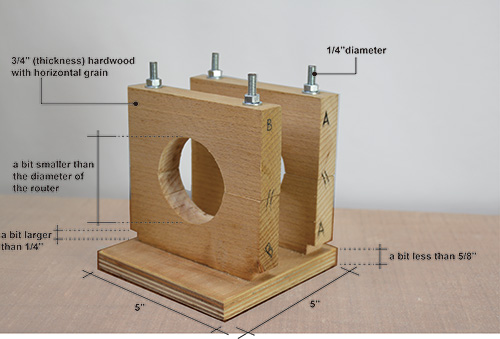
It turns out it is not too complicated to form grooves, create a pattern, or add inlays to a turned workpiece. Here is how I built the jig and how I achieved various results using different setups and their applications.
The Router Jig
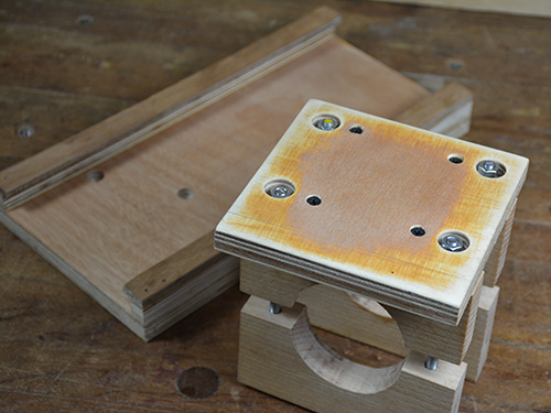
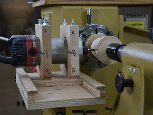
The jig I made is meant to be mounted in the lathe’s banjo. You can adjust the path of the router bit by moving the banjo and/or rotating the support.
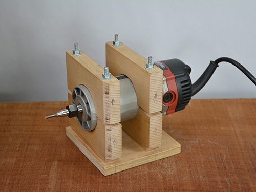
With a square base, the router can move in two different directions: along the length of the workpiece and towards the workpiece. When you combine these options, you will have several ways to create patterns and have many design possibilities.
Jig Components
 |
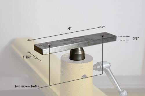 |
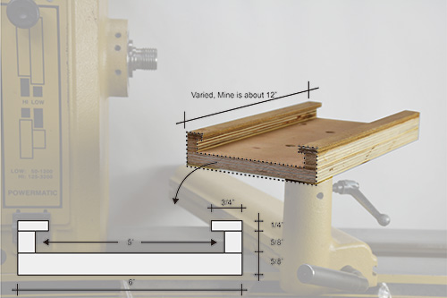
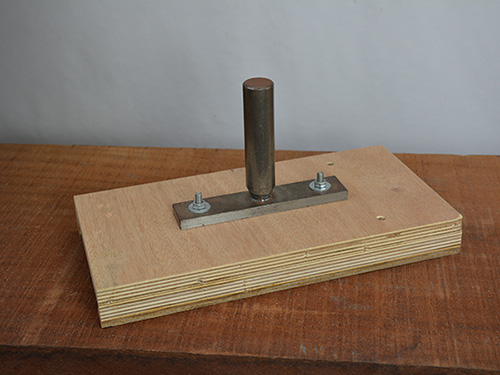
This jig comprises three main parts: the router holder, the track, and the support that fits into the lathe banjo.
 |
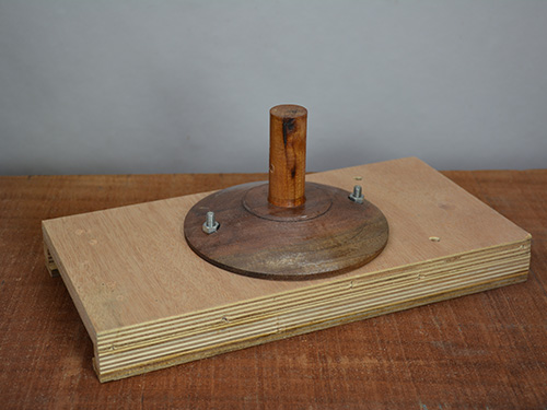 |
The photos show dimensions for my setup; you might need to adjust the size of the jig components, depending on the size of the workpiece and/ or your router.
Setup Concepts
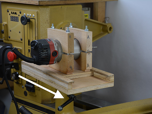 |
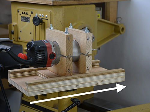 |
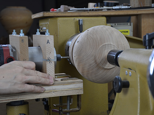
As noted, there are two fundamental ways to set the jig at the lathe. But depending on how the jig is presented to the workpiece, the results will vary. Even though the jig could be arranged at various heights for different cuts, I set the bit at center height (the height of the lathe spindle). Here, I have organized the setups in three different groups to show the different outcomes. Note that I always follow all the same safety rules that I would follow for using a router on a flat work.
 |
 |
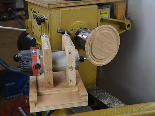
When setting the jig so that the router moves along the length of the workpiece, you can produce grooves on spindles. When you use the lathe’s indexing system, you can ensure even spacing between the grooves. This setup also can be used on the exterior of a bowl or vessel to make grooves for inlays or for texturing to create a visual rhythm — whether it’s a few grooves or a series of them.
 |
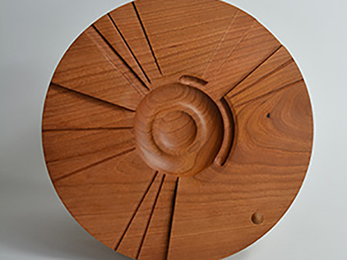 |
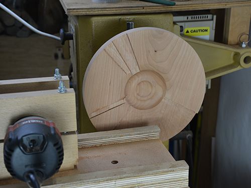
Sometimes I set the jig so that the router moves at an angle to the axis of the lathe. This setting is usually for a plate or for the top of the vessel. Besides creating the grooves, this setup also can add some geometric low relief to the surface.
 |
 |
To create shallow holes or indents in the workpiece, set the jig so that the router moves directly towards, or into, the wood. This approach is unlike the other two setups, which employ a more linear action, and can be used freehand or incorporated with the lathe’s indexing system.
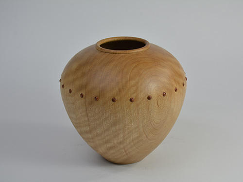
Another idea is to rotate the workpiece by hand after the router contacts the workpiece. In this way, you can create partial or continuous grooves around the circumference of the work.
Router Bits
You can also expand the variations when you use different router bits. Some of the results can be seen as texturing and some can be used for inlay. I use masking tape to prevent tearout. If the router bit burns the wood, I will either sand away the burn marks or take it as an embellishment opportunity and add color, pyrography, or texturing. As for inlay inserts, they can be ready-to-use wood strips from a store or custom-turned on the lathe. Here are some examples.
Straight Bit
 |
 |
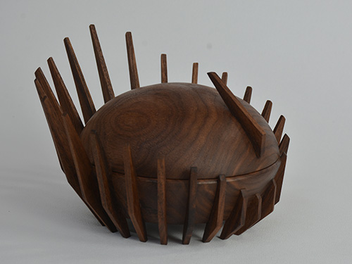
When using a straight bit to create grooves for inlays, the visual effects can be varied greatly just by changing the size of the bit. The left photo shows a series of inlays of the same width, while the right shows inlays of varied widths. You can also arrange the inlays in unexpected configurations. When I use ready-to-use wood strips from a store, I check their dimensions to make sure the ones I want are available.
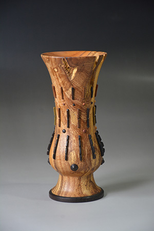
A straight bit is also used to bore shallow holes, as noted above.
Round Nose Bit
 |
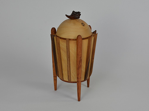 |
When you make grooves with a round nose router bit, the inlay insert can be turned on the lathe. In this way, you can fit different turned pieces together.
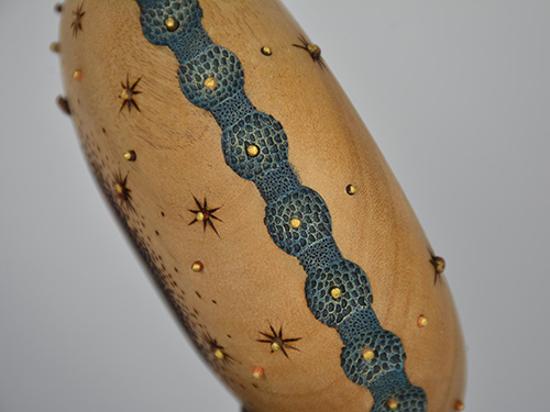
When using a round nose bit for other setups, you can achieve different creative results. This shows the overlapping of indents made with a round nose router bit.
V-groove Bit
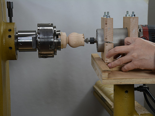
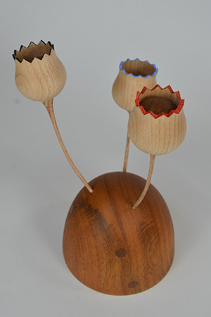
A V-groove router bit can create pointed grooves or angled indents. I used a V-groove bit to accent the edges of some tulip petals. You can also use this bit to add texture to the wood surface.
Plan Your Spacing
Before you turn on the router, you should know how many grooves/ holes you want to make, how big the inserts are going to be, and whether they are going to fit around your turned piece. Take the piece in Photo 11 as an example. I planned to cut thirty-six grooves, so I calculated the circumference by multiplying the diameter by pi, or 3.14. The bottom (smaller) diameter is 5-1/2″ (14cm), so the circumference is found by using this equation:
5.5″ × 3.14 = 17.27″ (44cm)
I then divided 17.27″ by 36 (my desired number of grooves/inlays) to reach 0.48″ (12mm) even spacing. I used wooden inlay strips that were 1/8″, or 0.125″ (3mm), wide. That left me with spacing of 0.355″ (9mm) between inlays, which I felt was a good proportion for this piece.
My lathe router jig helps me add more designs to my turned pieces, and I am sure there are lots of possibilities waiting to be explored. I hope this conceptual introduction will serve as a starting point for you to come up with your own designs by incorporating the use of a router at the lathe with the techniques you already use in your turning.
Cindy Pei-Si Young lives and teaches woodturning in Taiwan. She is a member of the AAW. For more, visit cindypeisiyoung.com or follow Cindy on Instagram, @young_woodturner.
