A couple of weeks ago I wandered into a little-used room in my parent’s house. There I found the broken bits of a table I had made a few years ago. Clearly, someone had tripped over the table and one of the three legs had broken right at the dovetail joint. A nearby clamp told me the rest of the story, which I assume went like this:
Don’t tell Ben. We’ll fix the table he made because he’s such a wonderful person. Oh, we feel so bad because surely he is our favorite son! We should make him his favorite meal and hope he never finds out.
Right?!?
Well, I saw the broken leg and knew that wood glue and a clamp weren’t going to fix it. The leg was attached with a sliding dovetail and broke along the long-grain. It wasn’t a clean break, so the remnants of the dovetail would need to come out and the leg would need to be reattached somehow.
Clean out the dovetail and make it whole
I dutifully brought the table to my shop, texted my mom that I’d fix it, and started chiseling out the carnage. At some point I realized the writing on the wall—this wasn’t a straightforward repair— and decided to document the process. Unfortunately for you, the reader, this was after I had chiseled out the dovetail in the base and planed off the broken bits on the leg. So we pick up this program that is already in progress.

Chiseling out the broken dovetail was a fairly simple affair. In hindsight, though, I should have drilled out most of the material in order to make chiseling easier. One key tool throughout this entire repair was my carvers vise. As you can see in the photos, mine is mounted on a guitar repair stand that is mounted to my floor. Any bench-mounted vise would have done the job of holding the work in the air, thus protecting the still-attached legs, but the soft, rotating jaws made this task (and the fact that I just mounted the vise there the week prior) all the more gratifying.
Once the receiving end of the dovetail was cleaned out, I took a scrap of cherry and routed a dovetail on each side of it. Well, I routed it on one side, went too far, and found myself using the other side of the scrap to get a tighter fit.

Using a mallet, I hammered the dovetail in.

After the glue dried, I sawed off the excess stock and planed it flush with the column. I should have given myself a high five for leaving the base of the column a hexagon and not turning it round. What I thought was a design decision was in fact just making my life a lot easier a few years down the road.
Make a mortise where there was once a dovetail
Now that broken bits were removed and filled, I could start on the joinery. I would have loved to maintain a sliding dovetail on this leg-to-column joint, but I would have needed to remake the entire leg so I could have an integral dovetail.
The only fix that seemed plausible was to create a floating mortise-and-tenon joint by routing a mortise in the column and in the leg.
Initially, I thought I would mortise the column on the router table, but the remaining legs hit the fence. I attached a lower fence on the router table, but I found I was left with just the edge of the hexagon referencing off the fence. After a dry run or two, I determined that the maneuver didn’t seem like a stable operation, and I decided I needed another plan.
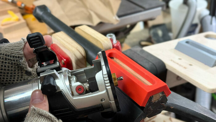
I needed a way to hold a router in a precise place and be guided along a precise path. Sadly, I had zero reference edges and barely enough stock to run a trim router on. I could have screwed a slotted board to the column in order to run the router guided by a router bushing. Instead, I decided to turn to one of my favorite woodworking tools: my 3D printer.
Using Fusion 360, my CAD program of choice, I created a piece that could easily straddle the hexagonal column.
 |
 |
 |
 |
I exported the file to my slicing program and printed it. The first jig I printed was a little loose on the column, so I updated the model and printed it again. In the following photos you can see the loose-fitting jig in the background.
I can hear many of you screaming, “Why would you go through all this trouble?” Well, modeling the jig took literally 5 minutes. Then my robot printed it while I was doing something else. Updating the model so it was perfect took one minute. Robot go brrrr … jig done.

I adhered the jig to the column with some double-sided tape.
While I trust my double-sided tape, I wanted to be absolutely certain the jig was not going to move, so I clamped the jig down to exert more pressure on the pressure-sensitive adhesive. (With PSA tape, the harder you squeeze it down, the better it sticks.)

Next, I chucked up a 1/4-in. bit in my trim router, outfitted it with a router bushing and routed out the mortise 3/16 in. at a time.

When I was done, I removed the jig and was left with a perfect mortise exactly where I wanted it to be. Better yet, I wasn’t worried at all about placement of the mortise, thanks to the 3D-printed jig!

Fine Woodworking Recommended Products

Freud Super Dado Saw Blade Set 8″ x 5/8″ Bore
Leaves a dado with a flat bottom and even performs excellent on plywood and melamine.

Festool DF 500 Q-Set Domino Joiner
This joinery machine revolutionized woodworking for so many. There is no easier way to get mortise and tenon joints—but it comes at a cost.

Olfa Knife
Comfortable plastic handle with a break off blade. A tool for breaking off the blade is built into the handy pocket clip.
Sign up for eletters today and get the latest techniques and how-to from Fine Woodworking, plus special offers.

